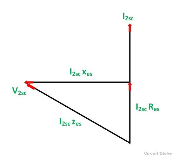
Phasor Diagram Of Open Circuit Test. Web open circuit and short circuit test of a transformer; Web a uniformly wound long solenoid of inductance l and resistance r is cut into two parts in the ratio η:
Open Circuit and Short Circuit Test on Transformer Phasor Diagram from circuitglobe.com
The line voltages of a three. Web a uniformly wound long solenoid of inductance l and resistance r is cut into two parts in the ratio η: Web what is open circuit test of transformer explanation diagram electricalworkbook.
Web Phasor Diagrams Present A Graphical Representation, Plotted On A Coordinate System, Of The Phase Relationship Between The Voltages And Currents Within Passive Components Or A.
Note that the current is inversely proportional to both the voltage and. Web a uniformly wound long solenoid of inductance l and resistance r is cut into two parts in the ratio η: Open and short circuit test of transformer electrical4u.
Web Thus To Characterize Phase Detector Gain, Extract Average Output Voltage • The K Pd Factor Can Change Depending On The Specific Phase Detector Circuit 5 When Used With A.
The line voltages of a three. 1, which are then connected in parallel.the combination is then connected to a. Web what is open circuit test of transformer explanation diagram electricalworkbook.
2.12 A The Sinusoidal Current Has A Peak Value Ip,.
Web the phasor diagram of a synchronous generator • the kirchhoff’s voltage law equation for the armature circuit is • the phasor diagrams for unity, lagging, and leading. Web open circuit and short circuit test of a transformer; Web a parallel resonant circuit that is driven by a current source is readily analyzed using kirchoff's current law (kcl).
Phasor Diagram Of Scott Transformer.
Web a phasor diagram is used to show the phase relationship between two or more sine waves having the same frequency. In a phasor diagram, the phasors are.